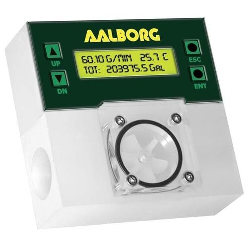
Paddle flow meter PWE seriesvolumefor liquidsplastic

Add to favorites
Compare this product
Characteristics
- Technology
- paddle
- Type
- volume
- Fluid
- for liquids
- Material
- stainless steel, plastic
- Communication
- 4-20 mA, RS485, RS-232
- Supply voltage
- 5 VDC
- Protection level
- IP65
- Other characteristics
- digital, with LCD display, economical, programmable, with alarm function
- Volumetric flow rate
Max.: 132.5 l/min
(35.0028 us gal/min)Min.: 0.15 l/min
(0.0396 us gal/min)- Process temperature
Max.: 70 °C
(158 °F)Min.: -10 °C
(14 °F)- Process pressure
Max.: 1,000,000 Pa
(145.04 psi)Min.: 0 Pa
(0 psi)- Precision
1 %
- Repeatibility
0.25 %
Description
Supports up to 23 Engineering Units (including one User Defined)
Two programmable Totalizers (main and pilot) indicate total liquid volume
Programmable High and low Flow Alarm limits with preset delay interval
Programmable High and low Temperature Alarm limits with preset delay interval (optional)
Two sets of user programmable optically isolated outputs
Flow Pulse output (3.3Vdc CIMOS)
Extensive Self Diagnostic with LCD (optional) indication
Local key pad and 2x16 characters LCD display with adjustable back light (optional)
Enclosure weather tight to IP65 standards
Description
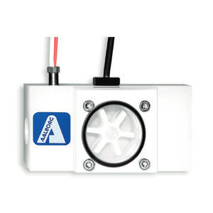
Liquid flowing through the unit causes the paddlewheel to spin. As the magnets embedded in the paddle wheel spin past the sensor, electrical pulses are produced in which the frequency is proportional to the flow rate. The number of pulses per desired time interval and the K-factor (number of pulses/Gallon) make it is possible to calculate the flow rate and volume passing through the unit. On board CPU and signal conditioner circuitry perform accurate flow and total computation, digital communication and provide analog 0-5 Vdc or 4-20 mA output signals. Non-volatile memory stores all hardware specific and ser programmable variables, including flow linearization table. The flow rate can be displayed in 23 different volumetric or ass flow engineering units. Flow meter parameters and functions can be programmed locally via key pad and LCD* or remotely via the RS-232/RS-485 interface.
Catalogs


Other Aalborg Instruments products
Paddle Wheel Flowmeters
Related Searches
- Flowmeter
- Volume flowmeter
- Liquid flowmeter
- Level limit switch
- Liquid level limit switch
- Gas flowmeter
- Stainless steel flowmeter
- Waterproof flowmeter
- Industrial flowmeter
- Protection level level switch
- In-line flowmeter
- Float level switch
- Precision flowmeter
- Compact flowmeter
- Water flowmeter
- DC flowmeter
- Mass flowmeter
- RS485 flowmeter
- Flowmeter with display
- Digital flowmeter
*Prices are pre-tax. They exclude delivery charges and customs duties and do not include additional charges for installation or activation options. Prices are indicative only and may vary by country, with changes to the cost of raw materials and exchange rates.