- Products
- Analog output card
- ACCES I/O Products, Inc.
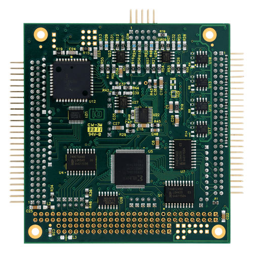
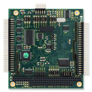
Analog output card 104-AO12-44-channel
Add to favorites
Compare this product
Characteristics
- Signal type
- analog
- Number of inputs/outputs
- 4-channel
Description
Analog Output:
-4 channels, 12 bit resolution
-Selectable unipolar or bipolar ranges 0-5V, 0-10V, ±5V, ±10V
-100K conversions per second
-3mA drive
Digital Input/Output:
-24 parallel bits (two 8 bit ports, two 4 bit ports)
-64mA sink, 32mA source (ports A and B)
-I/O pulled up to 5V
-Change of state detect on port C
-Type 82C55 PPI mode 0 (1 and 2 optional)
-Industry Standard 50 pin header
Timer/Counter: Type 82C54 (3×16 bit)
-Software Supported Modes:
-Three 16-Bit type 82C54
-Event counter, Frequency output
-Frequency and Pulse measurement
I/O Connectors:
-Two Industry Standard 50 pin headers
FLEXIBILITY
The following functions are available in many configurations giving the user the ability to specify exactly what’s needed. Interrupts are individually or globally enabled or disabled via software. A status register is provided to determine the interrupt source.
ANALOG OUTPUTS
Output ranges of 0-5V, 0-10V, ±5V and ±10V, are field selectable with jumpers. Note that four conversions may take place at once and that, since the D/As are double buffered, data for the next conversion may be loaded simultaneously.
COUNTER TIMERS
The circuit uses an 82C54 (3 sixteen bit counter/timers). The user has access to each counter/timer’s gate, clock, and output signals. The output of counter two can be used to generate an interrupt. The software package supports counting events, frequency output, pulse and frequency measurement.
DIGITAL I/O
The circuit uses an 82C55A PPI with mode 0 supported. Ports A and B (16 lines) are buffered and pulled up to 5V. Port C features Change of State detection.
Catalogs
No catalogs are available for this product.
See all of ACCES I/O Products, Inc.‘s catalogs*Prices are pre-tax. They exclude delivery charges and customs duties and do not include additional charges for installation or activation options. Prices are indicative only and may vary by country, with changes to the cost of raw materials and exchange rates.


