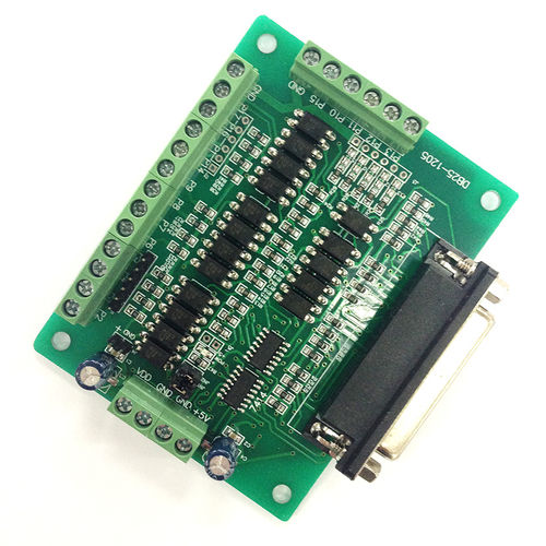
PC interface board multi-channel
Add to favorites
Compare this product
Characteristics
- Applications
- for PC
- Other characteristics
- multi-channel
Description
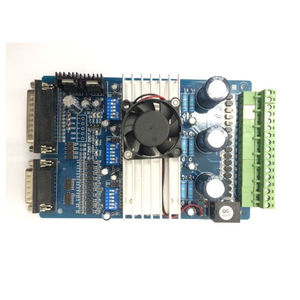
Instruction of Breakout Board
1、To connect the PC parallel port by the parallel cable of the priter
2、The power supply input port, can set up the single or double power supply
JN1&JN2 connected , is the case of the single power , the POWER + and
the isolating source will be connected, the GND and the isolating source
GND will be connected: if the JN1&JN2 is open circuit , the POWER + and
the isolating source will be cut off, the GND and the isolating source
GND will be cut off.
J4 is the GND and the POWER + of the isolationg source
3、Output connector, 12 wires OC( screw terminal output.
J1
J1 is the contact pin output, as the same as the terminal P2-P7, used
to connect the small driver.
4、The 5 channel input signal port can be connected to the external
mechanical switch, the proximity switch etc.
Through the P10-P15 , it can connect to the sensor and switch, and
it can realised the funcition by setting up the software.
The connection of the mechanical switch.
Catalogs
No catalogs are available for this product.
See all of ACT Motor GmbH‘s catalogs*Prices are pre-tax. They exclude delivery charges and customs duties and do not include additional charges for installation or activation options. Prices are indicative only and may vary by country, with changes to the cost of raw materials and exchange rates.


