- Metrology - Laboratory
- Metrology and Test Equipment
- Test system for automotive applications
- Bosch Engineering GmbH
Test system for automotive applications compact
Add to favorites
Compare this product
Characteristics
- Domain
- for automotive applications
- Configuration
- compact
Description
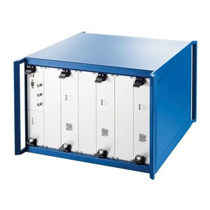
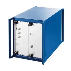
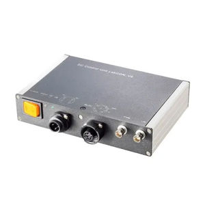
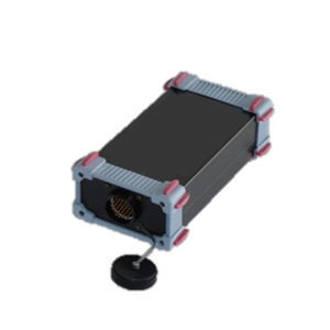
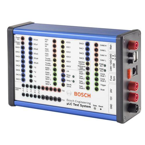
μLC Test System
• User-friendly user interface
• Functions can be added with expansion cards
• Extensive possibilities for test automation
• Compact, quickly deployable test system
• Simulation of all typical automotive sensors combined in one device
The new and modern hardware-in-the-loop test system µLC Test System is suitable for mobile application, measuring a compact 17 x 11 x 6 cm. Initial test setup typically takes under ten minutes, since the system allows for a simple test setup.
It is a compact open-loop test system for quality assurance of control unit development and combines the simulation of all typical automotive sensors and communication protocols in one unit. Its interface is user-friendly and enables an easy operation and evaluation.
The µLC Test System is especially used for automotive control units with typical interfaces for sensors and bus systems such as analog/digital inputs and outputs, PWM signals, SENT, CAN, LIN and speed sensors.
Engine Speed Simulation
• Up to 20,000 rpm
• Supported sensors: Hall, inductive, DG23i, TL4953
• Up to 2 crankshafts, up to 4 camshafts
◦ each is independently configurable
◦ auxiliary shaft
◦ -180 to 180° camshaft adjustment
• Oscilloscope trigger signal for easier monitoring
• Error simulation for engine position management EPM
Vehicle Busses
• 2 * CAN, up to 1 MBit/s,
switchable 120 Ohm CAN bus terminator
• LIN Master/Slave
• SENT, full J2716 Jan. 2012 standard
4 Outputs, alternative to PWM output
Analog Interfaces
• 8 * 10 bit DAC 0 to 5 V, max. 5 mA
Internal or external supply
• 4 * 12 bit DAC 0 to 5 V, max. 5 mA
Catalogs
No catalogs are available for this product.
See all of Bosch Engineering GmbH‘s catalogs*Prices are pre-tax. They exclude delivery charges and customs duties and do not include additional charges for installation or activation options. Prices are indicative only and may vary by country, with changes to the cost of raw materials and exchange rates.


