- Robotics - Automation - Industrial IT
- Industrial Software
- Design software
- CRYSTAL INSTRUMENTS

- Company
- Products
- Catalogs
- News & Trends
- Exhibitions
Design software calculationgraphicEDM
Add to favorites
Compare this product
Characteristics
- Function
- design, calculation, graphic, EDM, digital filter
- Applications
- process, multichannel analyzer
- Type
- real-time
Description
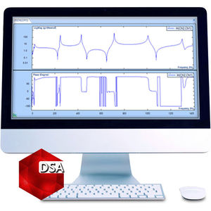
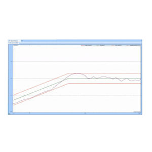
Real Time Digital Filters can be used to filter a measured signal in real time. Filter characteristics can be defined by the user to meet the requirements of a specific application. Real-time digital filters are applied in the data conditioning phase. The filters are designed with a graphic design tool and then uploaded to the front-end for real-time calculation. The graphic design tool defines the filter performance vertical axis with a dB scale. The horizontal axis is defined as relative frequency.
For example, a user might want to look at the energy distribution for a specific band of frequencies over time instead of for the entire frequency spectrum. This can be done by creating a band-pass filter and then applying an RMS estimator to the output of the filter.
The figure below shows a graphical representation of the process used to define a real time filter in the EDM software. The icon on the left, CH1 represents the native measured time stream. It is connected to an IIR Filter which computes a signal named iirfilter (ch1) which is connected to an RMS estimator. The output of the RMS estimator is a signal named rms(iirfilter(ch1)).
The Real Time Digital Filters option includes three types of digital filters: Finite Impulse Response (FIR), Infinite Impulse Response (IIR) and decimation filters. For the FIR and IIR filters you can specify: low-pass, high-pass, band-pass or band-stop filters with several different methods.
This chapter first explains some filter design theory and then introduces filter operations provided by EDM software and Spider hardware.
The goal of filter design is to calculate a series of filter coefficients based on user specified criteria
Catalogs
No catalogs are available for this product.
See all of CRYSTAL INSTRUMENTS‘s catalogsRelated Searches
- Automation software solution
- Management software solution
- Analysis software solution
- Process software solution
- Windows software solution
- Computer-aided design software
- Control software solution
- Real-time software solution
- Online software
- Design software solution
- 3D software solution
- Monitoring software solution
- Measurement software
- Interface software
- Industrial software solution
- Quality software
- Visualization software solution
- Automated software
- Network software solution
- Machine software
*Prices are pre-tax. They exclude delivery charges and customs duties and do not include additional charges for installation or activation options. Prices are indicative only and may vary by country, with changes to the cost of raw materials and exchange rates.


