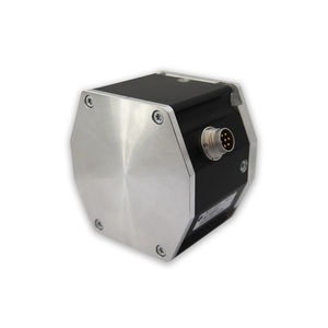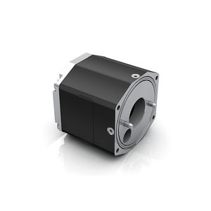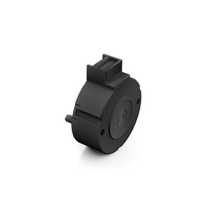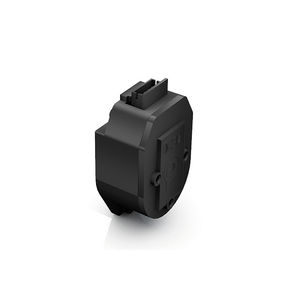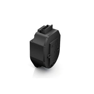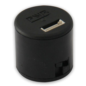
Incremental rotary encoder RE 56opticalnon-contactdigital

Add to favorites
Compare this product
Characteristics
- Type
- incremental
- Technology
- optical
- Construction
- non-contact
- Output signal
- digital
- Protection level
- IP30
- Applications
- for motors
Description
» Incremental encoders have no sliding contacts and are not subject to wear.
» A light-emitting diode, a slotted metal disc, and a photo-diode array from a photoelectric circuit.
» An integral logic produces two squarewave signals phased 90° to each other from the output of the photo diodes, with or without a reference impulse.
» Where the cable length between the encoder and controller is more than 2.5 m, we recommend the use of the RE..TI, fitted with an additional driver.
» The standard supply voltage for the incremental encoders is 5 VDC.
» As specials, 24 V versions are also available.
» An IP 54 cover is recommended as protection against external influences.
» In combination with motor BG 45 / BG 75 an integral magnetic resistive incremental encoder is available (ME integrated).
Channels : 2
Encoder ppr : 1000
Encoder Supply voltage V : 5
Protection class of attachment : IP30
Catalogs
Main Catalog Dunkermotoren
280 Pages
Exhibitions
Meet this supplier at the following exhibition(s):

Related Searches
- Dunkermotoren rotary encoder
- Dunkermotoren incremental encoder
- Dunkermotoren incremental rotary encoder
- Absolute rotary encoder
- Hollow-shaft rotary encoder
- Optical rotary encoder
- Magnetic rotary encoder
- Multi-turn rotary encoder
- Rotary encoder with SSI interface
- Digital output rotary encoder
- Dunkermotoren non-contact rotary encoder
- Dunkermotoren motor rotary encoder
- IP54 rotary encoder
- Hall effect rotary encoder
- Voltage output rotary encoder
- Photoelectric rotary encoder
- Dunkermotoren IP30 rotary encoder
*Prices are pre-tax. They exclude delivery charges and customs duties and do not include additional charges for installation or activation options. Prices are indicative only and may vary by country, with changes to the cost of raw materials and exchange rates.


