- Machine-tools
- Machine Tool Accessory
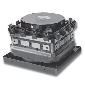
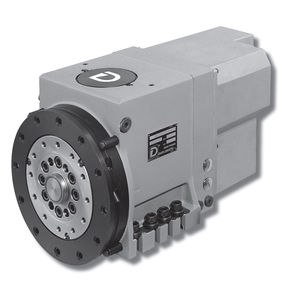
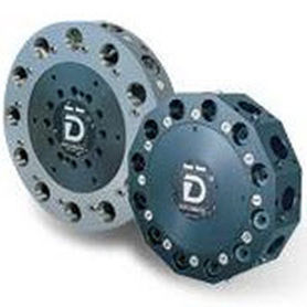
- Disc tool turret
- Duplomatic Automation
Disc tool turret TRM-N Seriesvertical-axiselectromechanical
Add to favorites
Compare this product
Characteristics
- Type
- disc
- Orientation
- vertical-axis
- Other characteristics
- electromechanical
Description
TRM-N series 2*
ELECTROMECHANICAL
VERTICAL AXIS TURRETS
TOOLHOLDERS CLAMPING DIN 69881-1
TRM-N / series 2*
INTERNAL KINEMATIC MOTION
A) Electric motor (three phase)
B) Reducing gearbox
C) Rotation and cam locking mechanism
D) Indexing solenoid
E) Indexing control switch
F) Preloaded locking springs
G) Front coupling
H) Locking control switch
I) Position proximity switches
L) Tool post
M) Coolant valves (optional)
TRM-N / series 2*
CYCLE DESCRIPTION
1. – Signals
To get a change of positions on the TRM-N turrets, the control equipment (usually a N.C. equipment) must control the
components mentioned below according to a well defined sequence (see wiring diagram on page 14).
• Motor (1)
• Indexing solenoid (3)
The following signals from the turret are provided for the driving of the positioning cycle:
– Angular position given by the proximity switch (61,62...)
– Indexing control switch (4)
– Locking control switch (5)
2. – Description of the operating sequence
This description refering to the diagram on page 15, gives the sequence to pass from position 1 to position 4 with counterclockwise
rotation.
As indicated by the cycle on page 15 the controls are to be performed according with the following sequence:
a) Starting of motor rotation in the unlocking direction
b) The turret disc rotating, when the proximity switch (6) of the pos.4 gives the signal, energize the solenoid (3).
N.B.: Between the reading signal and the energizing of the solenoid (3) the maximum lag time have not to exceed the value R1.
Catalogs
TRM-N
20 Pages
Related Searches
- Chuck
- Milling chuck
- Machining tool holder
- Collet tool holder
- Milling tool holder
- Intermittent index unit
- Tapping holder
- Horizontal rotary indexing table
- Machine tool rotary indexing table
- VDI chuck
- VDI tool holder
- Tool turret
- BMT tool holder
- CAPTO chuck
- Disc tool turret
- Machining center tool holder
- CAPTO tool holder
- Hydraulic tool turret
- Hydraulic rotary indexing table
- Direct-drive rotary indexing table
*Prices are pre-tax. They exclude delivery charges and customs duties and do not include additional charges for installation or activation options. Prices are indicative only and may vary by country, with changes to the cost of raw materials and exchange rates.


