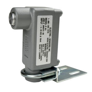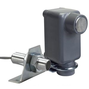
Rotational speed sensor 1101Hall effectnon-contactdigital output
Add to favorites
Compare this product
Characteristics
- Type of movement
- rotational
- Technology
- Hall effect
- Other characteristics
- non-contact, digital output, stainless steel
- Temperature range
Max.: 60 °C
(140 °F)Min.: -40 °C
(-40 °F)
Description
Features
NPN open collector, square-wave output
Zero speed operation with no signal loss
Non-contact, large gap distance sensing
Signal transmits up to 1,500 ft
Simple to install and set up
Powered by 5-24 VDC
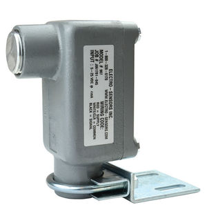
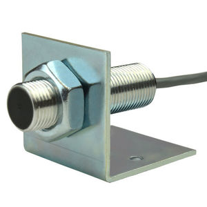
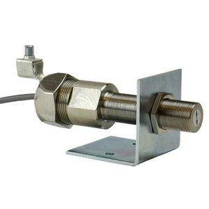
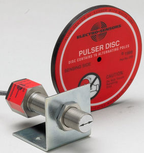
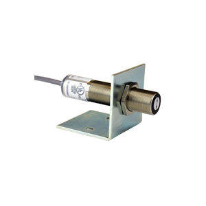
The 1101 Hall Effect sensor has a non-threaded stainless steel body, is supplied with a mounting bracket and 10 ft of 3-conductor shielded cable. It is commonly used with pulser discs or 60 pulse/rev magnet wheels.
These speed sensors use magnet-sensing Hall Effect IC's to produce a digital pulse signal to interface with speed switches, tachometers, counters, signal conditioners, or PLC's. Hall Effect sensors provide true zero speed operation with square-wave output and immunity to electrical noise.
A pulser disc or split collar pulser wrap with embedded magnets is mounted on the monitored shaft. As the shaft rotates, the magnets pass in front of the sensor causing the sensor to switch high and low, thus producing a digital pulse output. The sensors provide a digital square wave signal with a 50/50 duty cycle when used with pulse generators that have evenly spaced magnets of alternating polarity, such as Electro-Sensors Model 255 Pulser Disc. The recommended gap distance between the sensor and pulse generator is 1/4 inch +/- 1/8 inch. The gap flexibility makes the sensors tolerant of vibration, shaft run-out, misalignment, and industrial environments.
Catalogs
Related Searches
- Angular encoder
- Incremental encoder
- Proximity switch
- Incremental rotary encoder
- Cylindrical proximity switch
- Solid-shaft rotary encoder
- Hollow-shaft rotary encoder
- Industrial rotary encoder
- Magnetic rotary encoder
- Threaded proximity switch
- Analog panel meter
- Position panel meter
- Rotational speed sensor
- Magnetic speed sensor
- Non-contact rotary encoder
- Motion detector
- Standard rotary encoder
- Digital tachometer
- Tilt switch
- Non-contact proximity switch
*Prices are pre-tax. They exclude delivery charges and customs duties and do not include additional charges for installation or activation options. Prices are indicative only and may vary by country, with changes to the cost of raw materials and exchange rates.


