Harmonic analysis software test
Add to favorites
Compare this product
Characteristics
- Function
- harmonic analysis, test
Description
One particular concern with harmonics is the resonance condition in the power system. Because of the existence of both inductive components and capacitive components in the system, at certain frequencies, resonance conditions might occur at some buses. If the resonance occurs at a bus where a harmonic current is injected into the system, an overvoltage condition will be observed.
The ETAP Frequency Scan module is the best tool to investigate the system resonance problem. It calculates and plots the magnitudes and phase angles of bus driving point impedance over a frequency range specified by the user; thus, any parallel resonance condition and its resonance frequency can be clearly identified. The harmonic frequency scan study also allows users to tune their harmonic filter parameters and test the final results.
In Harmonic Frequency Scan module, the frequency range for scanning is defined by the user, which starts from the fundamental frequency and can go as high as the user needs.
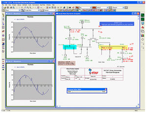
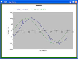
The results from the harmonic frequency scan study are reported in reports which includes the system input data, and a tabulation listing bus driving point impedances. The same tabulated information is also given on the one-line diagram, as well as in a plot format.
Catalogs
No catalogs are available for this product.
See all of Etap‘s catalogsRelated Searches
- Analysis software solution
- Computer-aided design software
- Real-time software solution
- Design software solution
- Interface software
- Quality software
- Automated software
- Network software solution
- Test software
- Creation software
- Modeling software
- Calculation software
- Flow software
- Architecture software
- Embedded software
- Instrument software
- Mapping software
- Data exchange software solution
- Backup software
- Electrical design software
*Prices are pre-tax. They exclude delivery charges and customs duties and do not include additional charges for installation or activation options. Prices are indicative only and may vary by country, with changes to the cost of raw materials and exchange rates.


