- Electricity - Electronics
- Electronic Component
- Single-pole switch
- EUCHNER GmbH + Co. KG
- Company
- Products
- Catalogs
- News & Trends
- Exhibitions
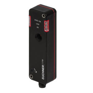
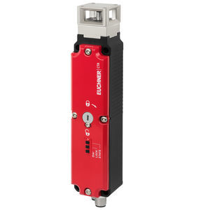
Safety switch CTP-I2-AS2B-U-HA-AZC-SJ-166889single-polerobustIP67

Add to favorites
Compare this product
Characteristics
- Number of poles
- single-pole
- Protection level
- robust, IP67, IP69K, IP69
- Other characteristics
- door, with guard locking, electromechanical, safety, compact
- Primary current
40 mA, 50 mA
- Voltage
Min.: 26.5 V
Max.: 31.6 V
- Operating temperature
Min.: -20 °C
(-4 °F)Max.: 55 °C
(131 °F)
Description
• Locking force up to 3900 N
• Category 4 / PL e according to EN ISO 13849-1
• Unicode
• Approach directions A, B and C (delivery state)
Guard locking actuated by power-ON and released by spring force (open-circuit current principle).
Control of the guard locking solenoid
The guard locking solenoid can be controlled via AS-Interface bus bit D0 or via the auxiliary power.
AS-Interface inputs
D0, D1
Door monitoring
D2, D3
Guard lock monitoring
Evaluation is performed via a safety monitor.
AS-Interface outputs
D0
Guard locking
LED function display
The ASI LED indicates the state of the ASi bus.
The STATE LED indicates the state of the switch.
The LOCK/DIA LED indicates if the door is locked and whether a fault has been detected in the switch.
VIDEO
Catalogs
No catalogs are available for this product.
See all of EUCHNER GmbH + Co. KG‘s catalogsOther EUCHNER GmbH + Co. KG products
Transponder-coded safety switches with guard locking
Related Searches
- EUCHNER single-pole switch
- EUCHNER technology switch
- Multipole switch
- EUCHNER electromechanical switch
- Rotary electric switch
- EUCHNER safety switch
- EUCHNER IP67 switch
- Tactile switch
- Metal switch
- EUCHNER plastic switch
- EUCHNER illuminated switch
- EUCHNER IP65 switch
- EUCHNER AC switch
- Lever electric switch
- EUCHNER IP69K switch
- EUCHNER ultra-rugged switch
- EUCHNER DC switch
- EUCHNER compact switch
- Mechanical switch
- IP40 switch
*Prices are pre-tax. They exclude delivery charges and customs duties and do not include additional charges for installation or activation options. Prices are indicative only and may vary by country, with changes to the cost of raw materials and exchange rates.


