- Products
- HEULE
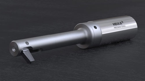
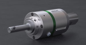
Automatic back spot facing tool BSF

Add to favorites
Compare this product
Description
The standard range consists of back counterboring tools for use with bore diameters ranging from 6.5 mm to 21 mm in 0.5 mm increments. The maximum possible counterboring diameter is 2.3 times the bore diameter. The tools can be activated both by internal coolant pressure ( min. 20 bar, max. 50 bar) or compressed air (min. 6 bar).
Construction
The BSF is specially designed for automatic operation and is ready for use immediately. It does not require a torque arm or any machine adaptations. The simple design of the back counterboring tool enables the swift replacement of individual parts and blades. Standard range carbide blades are coated and available in increments of 0.5 mm. The specially designed geometry of the tool ensures that chips and dirt are reliably flushed out of the blade window during counterboring.
Process steps description
The blade is extended by centrifugal force caused by the spindle rotation and retracted by activating the machine's internal coolant. Alternatively, if the machine is not equipped with internal coolant, there is also the option of activating the blade using compressed air. The counterboring tool is suitable for vertical and horizontal use.
The tool is moved in rapid feed in front of the bore. When the internal coolant is activated, the pressure on the control bolt causes the blade to retract. In this position, the tool moves through the bore. After turning off the internal coolant and activating the spindle rotation, the blade is extended. In working feed, the counterbore is now machined on the back of the bore. Once the blade is in the cut, the internal coolant can be switched on again
Once the tool has reached the desired bore depth
VIDEO
Catalogs
HEULE company brochure
16 Pages
*Prices are pre-tax. They exclude delivery charges and customs duties and do not include additional charges for installation or activation options. Prices are indicative only and may vary by country, with changes to the cost of raw materials and exchange rates.


