
- Products
- Catalogs
- News & Trends
- Exhibitions
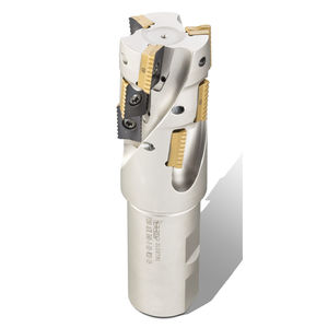
Interlocked side milling cutter HTF seriesinsertfacefinishing
Add to favorites
Compare this product
Characteristics
- Geometry
- interlocked side
- Construction
- insert
- Type
- finishing, face
- Other characteristics
- cutting edge, high-precision, high-rigidity, clamping, long, cutting
- Diameter
Max.: 160 mm
(6.3 in)Min.: 50 mm
(1.97 in)- Length
40 mm, 63 mm
(1.57 in, 2.48 in)
Description
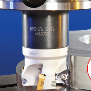
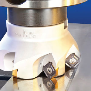
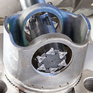
The new HTF D…-R-LN10 cutters carry standard HTP LN…1006 tangentially clamped inserts with 4 cutting edges.
The high surface quality is attained thanks to a very rigid clamping of the inserts together with the long and straight wiper edge.
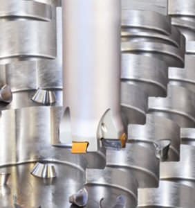
In addition, the inserts are positioned in gradual locations on the cutter in both radial and axial directions. This special design causes each insert to cut only a small portion of the material in both radial and axial directions.
Features
Designed for finish milling applictions for extra fine surface quality - up to 0.1 Ra (μm)
Carries a tangentially clamped insert with a large wiper effect
Each insert corner is located at varying diameter and height
Enables machining semi finishing and extra fine milling in a single pass
Vibration proof design
Reduced setup time, as the wiper effect is achieved without the need to adjust the wiper
The standard HTP LN.. 1006 insert that was originally designed for plungers is now used for the new finishing application
Coolant holes directed to each and every cutting edge
Special protective polished coating on cutter body for uninterrupted chip flow and protection against corrosion and wear
Notes for technologists and CNC programmers
The insert marked 1 defines the nominal diameter of the tool.
The slot 2 on the frontal side of the tool points at the pocket that carries the insert located at the maximum axial protrusion (marked as the largest number). The tool’s axial setup should be done according to this insert.
As the axial displacement between every consecutive insert is 0.05 mm, the maximum depth of cut for each tool can be calculated by multiplying the number of the tool’s teeth by 0.05 mm.
Catalogs
No catalogs are available for this product.
See all of ISCAR Tools‘s catalogsRelated Searches
- Milling tool
- Solid milling tool
- Drilling tool
- Steel milling tool
- Clamping milling cutter
- Solid drilling tool
- Milling tool with cylindrical shank
- Insert milling tool
- End mill milling tool
- Indexable cutting insert
- General purpose drill bit
- Cutting milling tool
- Solid carbide milling tool
- Face milling tool
- Carbide drilling tool
- Roughing milling tool
- Shell-end milling tool
- Indexable insert milling tool
- Corner radius milling tool
- High-performance milling tool
*Prices are pre-tax. They exclude delivery charges and customs duties and do not include additional charges for installation or activation options. Prices are indicative only and may vary by country, with changes to the cost of raw materials and exchange rates.


