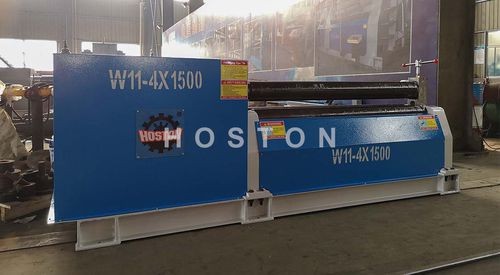
Structure style
• This is symmetric machine. The cylinder rolling is completed by the upper roller which pressing to the Iower one and the mutual rolling.
• The machine consists of two parts, the operation part and the transmission part which are welded at the whole pallet the operation part consists of left and right bearing housing one upper roller, two Iower rollers, lifting gears and some accessories. The Iower roller is the main one, upper roller can be adjusted at the height the transmission part consists with the main motor, speed-reducing motor and Other accessories.
• The Iower roller is driven by the main motor through the main reduce. The main reductor output Shaft transmits to the two Iower rollers through a group of gear wheel. The roller driving direction is switched by the main motor.
• The elevation movement of the upper roller is realized by the auxiliary motor through the auxiliary reductor, which drives worm and worm wheel under the left and right roller bearing to move automatically. makes the steel wire nut which is fixed on the worm wheel rotating, and completed by up and down movement of ball bearing screws accordingly.
• The offloading device is used after the round cylinder have been finished. Before leaving the left bearing seat, raises the upper roller to standard height, and make the upper roller stop with balance pull rod at the bottom of upper rollet Then draw out pin Shaft on the tilting bearing seat, overtum the tilting bearing seat, then the coiled product can emerge from one end of the upper roller.


