- Power Transmission - Mechanical components
- Bearing and Linear Guide
- Roller guide unit
- KADO Intelligent Technology (Shanghai) Company

- Products
- Catalogs
- News & Trends
- Exhibitions
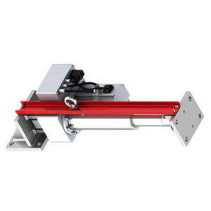
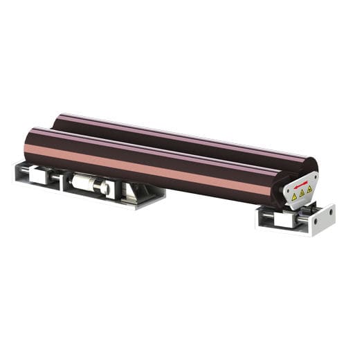
Roller guide unit compactfor inkjet printing head
Add to favorites
Compare this product
Characteristics
- Technology
- roller
- Other characteristics
- compact, for inkjet printing head
- Rail length
Max.: 3,000 mm
(118.11 in)Min.: 400 mm
(15.75 in)- Load
500 N, 1,000 N, 3,000 N
- Operating temperature
Max.: 50 °C
(122 °F)Min.: 10 °C
(50 °F)
Description
bstract:They consist of a fixed base frame and a movable guide frame. The latter accommodates one or two positioning rollers and swivels round an imaginary pivot point on the infeed plane. When the feed path is deviated, the guiding roller frame is translated one side so that the material enters the correct set position at the next roller. Based on the working principle of the displacement correcting roller frame, the displacement correcting roller frame needs a sufficiently long feed span and discharge span.
A-A Stress distribution of material width at feed end 1 Rotating point
B-B Stress distribution of material width at discharge end 2 Feed end roller
K Material width correction quantity 3 Frame
α Maximum deviation correction range ±5° 4 Electro-eyes
σ1 Basic stress of material width 5 Fixed roller
σ2 Stress distribution due to swing of the deflection roller at the feed end
σ3 Stress distribution due to swing of the deflection roller at the discharge end Feed length from
L1 to rotation point Feed length between barrels Feed length from
L2 rotation point to rotary advance roller
L3 feed length = feed distance = 1.8 times to 2 times the maximum width of the material
L4 discharge length = feed distance = 0.5 times to 1 time the maximum width of the material
Guiding accuracy - ±0.1mm
Roller diameter D - 100/120/160/200mm
Operating voltage - 24V DC
Respondence speed Max 30mm/s
Other KADO Intelligent Technology (Shanghai) Company products
Web Guiding System
*Prices are pre-tax. They exclude delivery charges and customs duties and do not include additional charges for installation or activation options. Prices are indicative only and may vary by country, with changes to the cost of raw materials and exchange rates.


