- Company
- Products
- Catalogs
- News & Trends
- Exhibitions
Analysis software EasyREFRACTphasequalitytest
Add to favorites
Compare this product
Characteristics
- Function
- analysis, phase, quality, test, control, editing, file import/export, locating
- Applications
- process, printing
Description
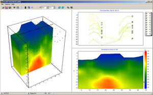
INTERPRETATION OF SEISMIC REFRACTION TESTS
Software for the interpretation of seismic refraction tests, was implemented to ensure the quality standards of GeoStru including ease of use, full control over operational phases, the preparation of the automatic report printing and the ability to export all the charts and graph.
The definition of the array geometry is extremely flexible and does not impose constraints on the number of shots to be used in the analysis.
The software is able to guide the user through the analysis phases offering the full control of the operative process. The program has implemented an efficient locating system that allows editing the aerial photo of the research area.
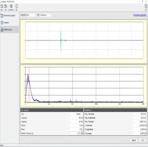
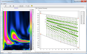
Field data is extracted directly from the files generated by loggers (in formats like SEG2, SEGY, SU, etc.) and plotted to give the user the identification of the first arrivals, that can also be entered manually or by copy/paste.
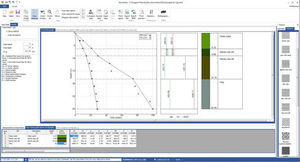
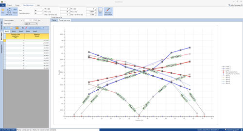
As a function of the identification of the first arrivals, the software is able to operate the regression analysis and identify the time travel curve. Through this analysis phase arrival times are assigned to the correct refractors.
After building the time travel curve and having identified the propagation velocity of the seismic signal in the different layers of the soil, the Generalized Reciprocal Method is applied. This method is based on the research, in the time-distance diagram, of an optimal distance between geophones XY, in such way that the seismic rays coming from opposing shot points, positioned in a symmetrical manner at the ends of the array, arrive from the same point of the refractor on the geophones placed in X and Y.
Catalogs
No catalogs are available for this product.
See all of M.A.E. S.r.l.‘s catalogsRelated Searches
- Automation software solution
- Management software solution
- Analysis software solution
- Process software solution
- Windows software solution
- Control software solution
- 3D software solution
- Measurement software
- Interface software
- Quality software
- Visualization software solution
- Automated software
- Development software
- Engineering software
- Test software
- 2D software
- Creation software
- Reporting software solution
- Modeling software
- Calculation software
*Prices are pre-tax. They exclude delivery charges and customs duties and do not include additional charges for installation or activation options. Prices are indicative only and may vary by country, with changes to the cost of raw materials and exchange rates.


