Torque limiter with coupling STL seriesfrictionmechanical
Add to favorites
Compare this product
Characteristics
- Operation
- friction, mechanical
- Other characteristics
- with coupling
- Torque
Min.: 16.66 ft.lb
Max.: 1,011 ft.lb
- Rotational speed
1,325 rpm, 1,750 rpm
(8,325.22 rad.min-1, 10,995.57 rad.min-1)
Description
MECHANICAL FRICTION TORQUE LIMITER MECHANISMS WITH COUPLINGS
Overload Protection Between Two Supported Shafts with No Angular or Parallel Misalignment
Function: Overload Protection
Drive Arrangement: Shaft to Shaft, No Angular Misalignment and/or Parallel Offset
Torque limiter mechanism is through bored and keyed to connect to a fully supported shaft.
Coupling is bored and keyed to connect to a fully supported shaft.
Operation
Continuously engaged friction torque limiter slips when the torque setting is exceeded. Continues to slip until the overload ceases.
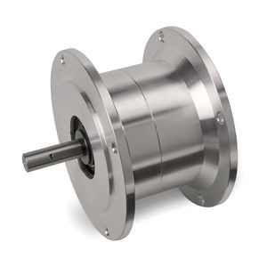
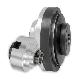
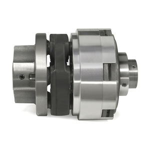
Each half of the assembly, (1) torque limiter mechanism and (2) the coupling/sleeve assembly, is attached to a fully supported shaft.
The tabs on the outside of the friction discs in the mechanism slide into the slots in the coupling/sleeve assembly, creating a connection for the transfer of rotary motion from one shaft to the other.
IMPORTANT: If precise alignment of the two shafts cannot be obtained, consider a flexible torque coupling model.
Application
Momentary overload protection.
Torque limiters are not recommended in continuous slip or tension control applications. Consider a SensiFlex® tension control clutch or brake.
Maximum RPM varies by model. Please consult the detail sheets. Consult engineering if the intended application exceeds the listed maximum RPM.
Design Features
No reset is required after torque limiter slips.
The slip torque setting can be adjusted.
Both the torque limiter mechanism and coupling/sleeve assembly are bored and keyed to fit any shaft size up to the maximum shown (US & Metric).
Catalogs
No catalogs are available for this product.
See all of Mach III Clutch, Inc.‘s catalogsOther Mach III Clutch, Inc. products
Mechanical Friction Torque Limiters
Related Searches
- Friction brake
- Spring brake
- Friction clutch
- Overload clutch
- Safety brake
- Pneumatic brake
- Spring activated brake
- Spring clutch
- Mechanical overload clutch
- Pneumatic clutch
- Failsafe brake
- Friction slip clutch
- Motor brake
- Multiple-disc clutch
- Safety torque limiter
- Adjustable brake
- Multiple-disc brake
- Combined clutch-brake unit
- Friction combined clutch-brake unit
- Tension control brake
*Prices are pre-tax. They exclude delivery charges and customs duties and do not include additional charges for installation or activation options. Prices are indicative only and may vary by country, with changes to the cost of raw materials and exchange rates.


