- Metrology - Laboratory
- Metrology and Test Equipment
- 3D scanning system
- Princeton Applied Research
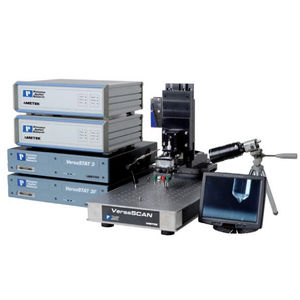
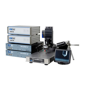
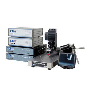
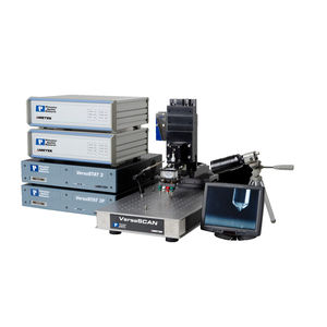
3D scanning system LEISmeasurementlaserelectrochemical
Add to favorites
Compare this product
Characteristics
- Number of axes
- 3D
- Applications
- measurement
- Technology
- electrochemical
Description
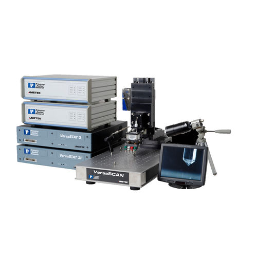
The VersaSTAT 3F applies an AC voltage to the sample emerged in electrolyte. This "global" voltage generates AC current to flow at the electrode / electrolyte interface. A dual-element probe is positioned in solution close to the surface of the sample. The electrometer measures a differential voltage measure between the two measurement elements as a measure of local voltage-drop in solution. This voltage-drop exists in solution because of current flow from local reactions at the sample, the resistance of the electrolyte and the spatial separation of the dual measurement elements.
The VersaSCAN’s electrometer inputs its measured voltage to the Auxiliary Differential Voltage Input available with the VersaSTAT 3F.
Software integration converts the measured local voltage-drop at the probe to local AC current.
he ratio of local measured current to the global applied voltage gives the localized impedance magnitude and phase shift.
There are two different test methods for the experimentalist to use LEIS to evaluate their samples
A) Chart the local response of a sample from a range of applied AC frequencies in a single location. Data can be viewed in either a Bode or Nyquist representation.
B) Create a series of data maps to characterize an AC response as a function of probe position. Data can be used to create a map, using either Magnitude or Phase as the response
VIDEO
Catalogs
Product Catalog
11 Pages
Other Princeton Applied Research products
Scanning Electrochemical Systems
*Prices are pre-tax. They exclude delivery charges and customs duties and do not include additional charges for installation or activation options. Prices are indicative only and may vary by country, with changes to the cost of raw materials and exchange rates.


