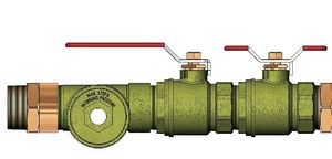
Water hydraulic pump testopen
Add to favorites
Compare this product
Characteristics
- Applications
- water, test
- Other characteristics
- open
- Pressure
Max.: 16 bar
(232 psi)Min.: 0 bar
(0 psi)
Description
Components
• Rcl/2 inlet unions
• RC1/2 lockable ball valves
• 3 mm flow restrictor
• 0-16 bar glycerine gauges c/w no loss connectors
• 1/2" check valves in copper bypass line
• 0-14 bar pressure switch (double) for duty and stand by pumps
• 0-14 bar pressure switch for jockey pump
• 1/2" galvanised tube and fittings
Installation & maintenance
• Assembly to be located where it will not be subjected to freezing or extreme temperatures. All electrical
connections to be made by qualified staff.
• Pressure switch can be set after installation with system at operating pressure. Close the top inlet valve
and slowly open the bottom test valve to reduce gauge pressure to the desired level. Close test valve and
adjust pressure switch. Double switch units require the same procedure but the switch not being set must
be disconnected from the circuit at the pressure switch plug.
• Alternatively, these double switched units can be connected via a spring loaded inhibitor switch which will
then accommodate both initial setting and weekly tests without the need to disconnect the switch that is
not being set or tested.
• To test pump operation, close the top inlet valve and slowly open bottom test valve to start pump. Top
inlet valve to be in the open position for normal operation
• Unit is designed to be maintenance free. However pressure switches and gauges can be replaced by
isolating the pump, closing top inlet valve and draining the unit via bottom test valve.
Catalogs
No catalogs are available for this product.
See all of ROLLAND‘s catalogs*Prices are pre-tax. They exclude delivery charges and customs duties and do not include additional charges for installation or activation options. Prices are indicative only and may vary by country, with changes to the cost of raw materials and exchange rates.


