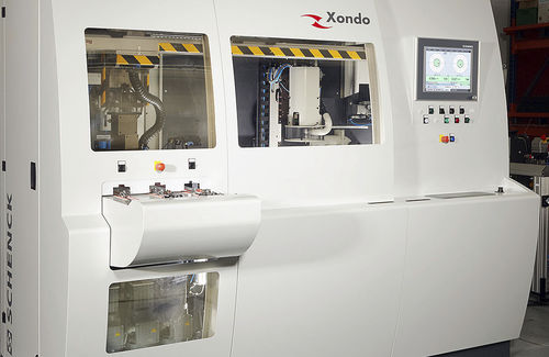
• Fully automatic balancing of turbine wheel shaft assemblies
• Digital measured data processing and numerically controlled unbalance correction
• Gantry loader and commercially available conveyor system
• Easy change over to other rotor types
• Short cycle times
• Most compact layout
• Easy movable as a single block
Sequence of operations
• The work-piece is taken from the transfer equipment and loaded into the measuring station.
• Automatic measuring run. Calculate and transfer measured values to the correction station, brake to zero rpm
• Remove the rotor from the measuring station and load into the correction station.
• Automatic correction: clamp, index to the correction position of the 1st plane, controlled grinding of a sector. Index to the corretion position of the 2nd plane, repeat the grinding process and unclamp.
• Transfer the rotor to the measuring station and start the check run. If the rotor is not in tolerance after the 1st correction step further correction steps can be carried out.
• Remove the work-piece and unload it to the out feed conveyor
Range of application
Measurement and correction of dynamic unbalance of machined turbocharger turbine wheels. Use of the machine in mid- and large-volume production.
Fully automatic unbalance measurement and correction by grinding in two planes and with multiple correction steps. Loading and unloading by gantry loader.
Design
Multi-station machine with measuring and correction station and fully automatic operating sequence.


