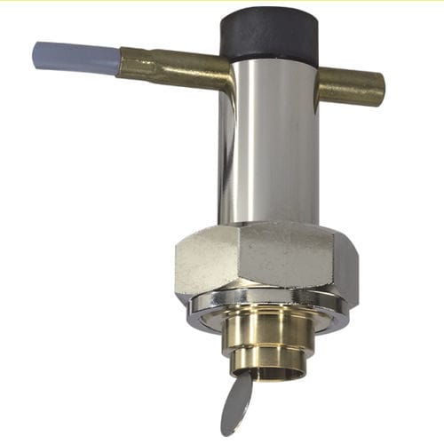
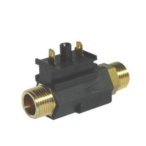
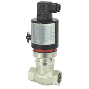
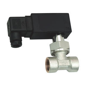
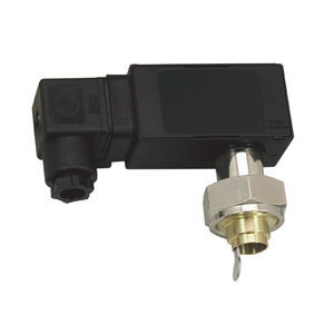
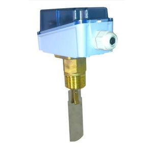
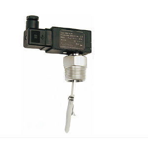
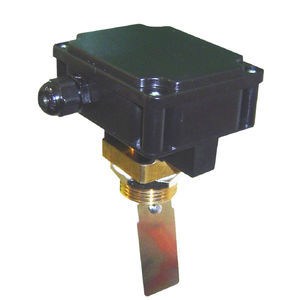
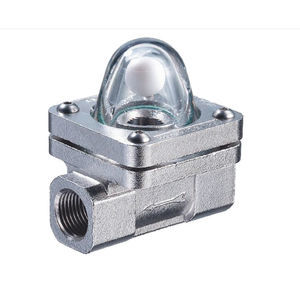
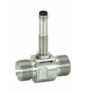
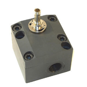
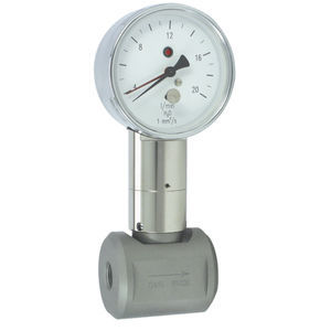
The devices function via the principle of a spring-supported paddle, and the magnetic triggering of a reed switch.
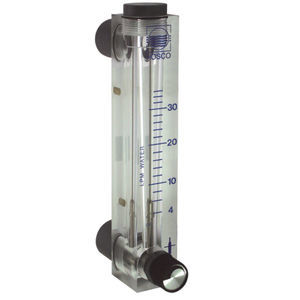
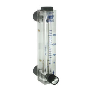
Ranges
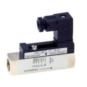
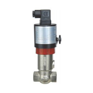
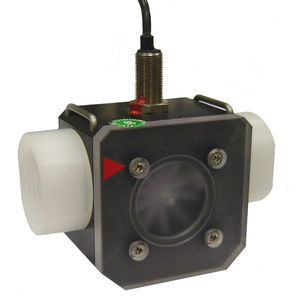
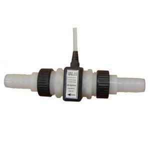
Details in the table correspond to horizontal inwards flow with decreasing flow rate. UR2 (Plastic switching unit) is adjusted in the factory; please specify switching value.
Handling and operation
Note
●Include straight calming section of 5 x DN in inlet and outlet
●If the media are dirty, install a filter (use magnetic filter for ferritic components).
●It must be ensured that the values given for voltage, current, and power are not exceeded.
●When switched on, a load must be connected in series.
●The electrical details apply to ohmic loads. Capacitive, inductive and lamp loads must be operated using a protective circuit.
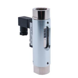
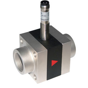
Adjustment UR1 - loosen bolts,
push the switching current tube into the desired position. Retighten the bolts. Normally closed (n.c.) or normally open (n.o.) as per table "Technical data"
Options
●Switching ranges for oil or gas
●Special quantity
●Adhesive PVC fitting
Ordering information
●Specify direction of flow, medium, and switching range, UR1 or switching value UR2.
●For UR2 specify normally closed (n.c.) or normally open (n.o.).
●For oils, state viscosity, temperature and designation (e.g. ISO VG 68) (enquire about range).
●For gases, state pressure (relative or absolute), temperature and medium (e.g. air) (enquire about range).