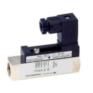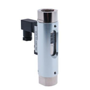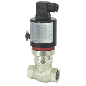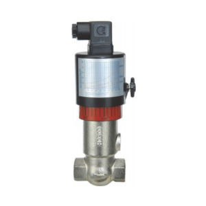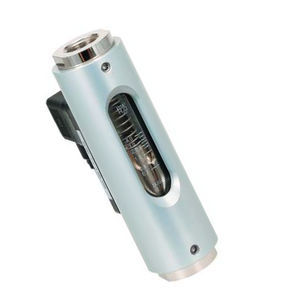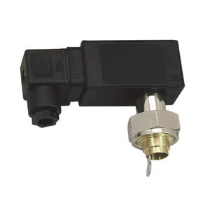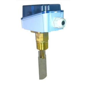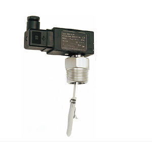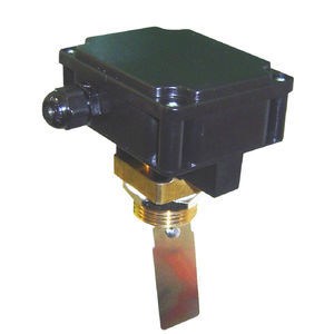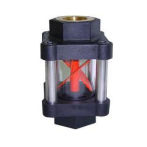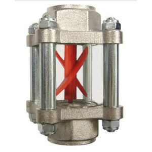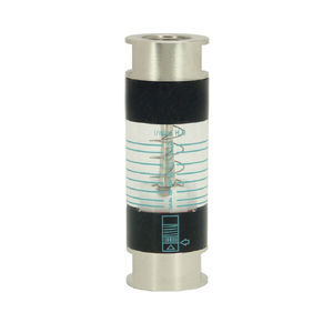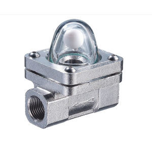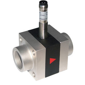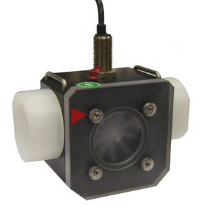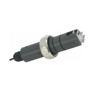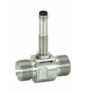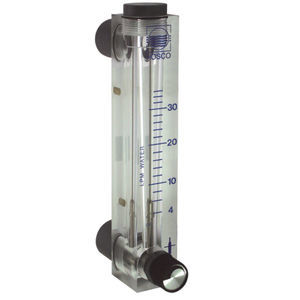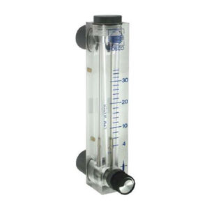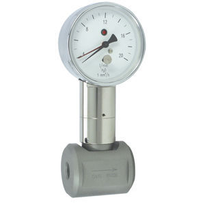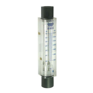
Magnetic flow switch UM3K-Vpaddlefor liquidsreed switch


Add to favorites
Compare this product
Characteristics
- Technology
- magnetic, paddle
- Fluid
- for liquids
- Other characteristics
- reed switch, low-pressure, stainless steel, brass, PVC, threaded, IP65
Description
The devices function via the principle of a spring-supported paddle, and the magnetic triggering of a micro switch.
Handling and Operation
Note
●Include straight calming section of 5 x DN in inlet and outlet
●When tightening the union nut, the connection piece must be countered using an open-ended spanner (SW 19).
●If the media are dirty, install a filter (use magnetic filter for ferritic components).
●It must be ensured that the values given for voltage, current, and power are not exceeded. ●When switched on, a load must be connected in series.
●The electrical details apply to ohmic loads. Capacitive and inductive loads must be operated using a protective circuit
Adjustment
To adjust, open the slider. Adjustment is made using the adjustment screw with a lengthways slot; this is located under the valve.
Turn clockwise for a lower switching point; turn anticlockwise for a higher switching point.
After adjustment, close the slider again.
Example: The adjustment range 20 to 27 l/min corresponds to 7 l/min Adjustment option in 7 revolutions. Adjustment is therefore 1 l/min for each revolution.
Options
●Connection for round plug-in connector
●Signal lamp red or red/green in the plug DIN 43650-A
●Gold contact 125 V AC / 30 V DC, 100 mA
●Protective bellows ●Switching ranges for oil or gas
●Special values
●Adhesive PVC fitting
Ordering information
●Specify direction of flow, medium, and switching range.
●For oils, state viscosity, temperature and designation (e.g. ISO VG 68) (enquire about range). ●For gases, state pressure (relative or absolute), temperature and medium (e.g. air) (enquire about range).
Catalogs
No catalogs are available for this product.
See all of VAL.CO srl‘s catalogsRelated Searches
- Flowmeter
- Liquid flowmeter
- Pressure transmitter
- Level limit switch
- Pressure gauge
- Level probe
- Liquid level limit switch
- Analog pressure transmitter
- Liquid level probe
- Gas flowmeter
- Stainless steel flowmeter
- Analog pressure indicator
- Pressure switch
- Waterproof flowmeter
- Relative pressure transmitter
- Membrane pressure transmitter
- Waterproof pressure transmitter
- Stainless steel pressure transmitter
- Analog level probe
- Mechanical pressure switch
*Prices are pre-tax. They exclude delivery charges and customs duties and do not include additional charges for installation or activation options. Prices are indicative only and may vary by country, with changes to the cost of raw materials and exchange rates.


