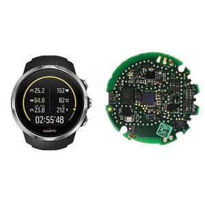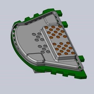
RFI shielding EMIboard levelcage
Add to favorites
Compare this product
Characteristics
- Options
- EMI, RFI, board level
- Type
- cage
- Applications
- for circuit boards
Description
The typical one-piece board level shield consists of a stamped metal can (usually a rectangle) that is soldered directly to ground pads or through grounding vias on the PCB. There is a very wide range in the degree of soldering points between the shield and the ground plane of the PCB. For example, in the most extreme case, the shield can be continuously soldered around the perimeter of the can where it mates to the board. This essentially provides a complete Faraday cage and provides among the highest level of shielding effectiveness. Other methods include solder pads every 2-4mm around the perimeter and pins that are soldered on the back side of the board as these pins protrude through vias or through holes.
The advantages of one-piece board level shields is that they can provide a high level of EMI/RFI shielding effectiveness and they can be among the lowest cost solutions.
However, the disadvantages can be numerous. If the shield can is installed during the reflow process, you lose the ability to inspect and/or rework the board after reflow. If the shield is installed after reflow, it can be a very costly and timely manual process, it can lead to de-soldering of adjacent components and it is not removable and replaceable without subjecting the board and components to additional heat, which always introduces risk.
In order to ensure a robust solder joint between the one-piece shield and the PCB, there are stringent co-planarity requirements, which are difficult to achieve and become more challenging as the shield size increases.
Improved One-piece EMI Shielding with XGR Technologies SnapShot® EMI Shield
Catalogs
No catalogs are available for this product.
See all of XGR Technologies‘s catalogs*Prices are pre-tax. They exclude delivery charges and customs duties and do not include additional charges for installation or activation options. Prices are indicative only and may vary by country, with changes to the cost of raw materials and exchange rates.


