- Industrial machines and equipment
- Heat Exchanger and Refrigeration
- Desuperheater
- Zaklady Automatyki POLNA S.A.

- Products
- Catalogs
- News & Trends
- Exhibitions
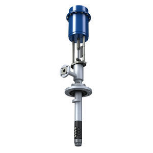
Desuperheater SP-1
Add to favorites
Compare this product
Description
The cooling water is supplied to the injection nozzle(s) through the feeding flange stub pipe or with a welded connection. The amount of cooling water supplied to the steam pipeline is adjusted by changing its pressure at the inlet to the desuperheater.
We would also like to invite you to read the study concerning “Elements of the Reduction and Cooling Stations”
We can adjust construction (design) of control valve to your individual needs.
Materials - - body: S355J2G3 ; (1.0570); 13CrMo 4-5 ; (1.7335); - nozzles: X6CrNiMoTi 17-12-2 ; (1.4571); Other materials - upon request.
Flow coefficient - Kv max 1.0
Rangeability - 3:1
compact structure for installation between flanges
lack of movable parts
scope of adjustment up to max Kvs 1.0
adjustment 3:1 of control efficiency for cooling water pressure
diameter of the steam pipeline: DN32 ... DN150 , PN16, 25, 40, 63, 100 diameter of the cooling water pipeline: DN25/ 40/ 50; PN40; 63; 100; 160 Other DN / PN values, as well as the flange connections as per the ANSI norms - upon request.
Other Zaklady Automatyki POLNA S.A. products
Steam desuperheaters
*Prices are pre-tax. They exclude delivery charges and customs duties and do not include additional charges for installation or activation options. Prices are indicative only and may vary by country, with changes to the cost of raw materials and exchange rates.


